Introduction
As part the overhead switch replacement project to improve the efficiency of one of our customers’ overhead network, there was a requirement for pairs of Rapier GX Load Break Switches to be provisioned with the ability to automatically maintain supplies to essential loads following loss of supplies. The configuration of load break switches for supplying essential loads is shown in figure 1.
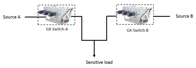
Figure 1: Configuration of load break switches for supplying essential loads
Power continuity is a critical power quality issue, and a disturbance that occurs in the distribution network often leads to discontinuity of power. As distribution networks are commonly designed with two power supplies, bus transfer schemes are often used during a scheduled maintenance or following a power system fault.
Challenge
As part of the project to deliver a full turnkey solution replacing the existing overhead load break switches with new Rapier GX switches integrated Gemini 3 remote terminal units (RTUs) an additional requirement was to provide an automatic transfer of source scheme to further improve quality of supply to essential loads.
An automatic transfer of source system (ATS) continuously monitors the redundant power sources and performs controlled switching for the changeover of sources, minimising the power supply outage in MV secondary distribution network. This scheme is used to protect critical loads that are unable to tolerate a sustained loss of voltage (e.g. hospitals).
These types of transfer schemes have been widely accepted in power industry to improve system reliability. However, in this particular application the primary overhead switches and integrated RTUs are geographically separated. A combination of two sets of Rapier GX switch /Gemini 3 RTU configurations were required to manage and co-ordinate the automatic transfer of power source to a common essential load. The challenge was to achieve this level of functionality over a long distance, using distributed processing whilst communicating with each other and the control centre.
The Gemini 3 RTU receives 3 phase current inputs from the Rapier GX switch, and 3 phase VT inputs from a pole mounted 3-phase VT. A single phase from this VT also provided the power source to the RTU. The Gemini 3 RTU also had its own built-in UPS for when the line was dead.
Solution
The solution was to re-use as much as possible the common automatic transfer scheme logic used in ring main unit applications, and to distribute this processing over the Gemini 3 RTUs used for the automatic transfer of source scheme. Gemini 3 RTU’s used IEC 61499 to model the control system. The configuration of the two Gemini 3 RTUs is shown in figure 2.
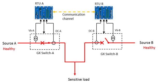
Figure 2: Configuration of Gemini 3 RTUs
IEC 61499 is an event driven programming language allowing distributed and synchronised processing. This means that the transfer of source system scheme can work over the two sets of Gemini 3 RTUs allowing a co-ordinated switching between the unhealthy to healthy power source to maintain continuity of supply to an essential load. As IEC 61499 is event driven, the two RTUs will concurrently respond to the loss of healthy supply event as soon as it happens and determine the best course of action. Utilising a fast communication network between the two RTUs supports the distributed processing as if it occurs on a single RTU.
IEC 61499 provides a system modelling capability on the Gemini 3 platform. The programming unit in the Gemini 3 RTU is a function block. The programming unit of the IEC 61499 is also a function block. It is from these function blocks complex control applications can be built and tested, as well as easily documented.
The combinatorial logic to form the ATS scheme becomes an IEC 61499 function block in both RTUs which can then become a standard function within the Gemini 3 RTU configuration. This portability is applied across the Gemini 3 range as the ATS becomes a library function that hooks into the standard Gemini 3 configuration. IEC 61499 is considered more suitable for these types of sequencing applications than the equivalent IEC 61131 because of the event driven and distributed processing features.
The application is a network of interconnected function blocks, responding to the loss of voltage supply from either of the voltage sources. The ATS scheme was then mapped to the physical devices used for the application, in this case the two Gemini 3 RTUs. IEC 61499 supported the distributed application by utilising the User Datagram Protocol (UDP), communicating over optical fibre between the two Gemini 3 RTUs on the same sub-net. UDP is a standard low latency protocol which is complemented by the error checking and control logic performed by the IEC 61499 in the RTUs.
Because this application is performing automated remote switching it is important that fail safe mechanisms were in place. The fail-safe will automatically disable and lock out the ATS scheme during the following scenarios:-
- A manual change of status of either Rapier GX switch
- A communication failure between the two Gemini 3 RTUs
- If either RTU is in local operation mode
- If either RTU is restarting or rebooting
- If either Rapier GX switch is disabled or has low gas pressure
- An overcurrent being detected on either Rapier GX switch
The outcome
The ATS scheme logic flow is illustrated in figure 3. The X-axis is an indication of time; the actual timings are configured as part of the ATS scheme. The ATS scheme is initiated following a loss of supply from source A, and source A being isolated by the automatic opening GX switch A. Supply to the load is restored from source B following the automatic closing of GX switch B.
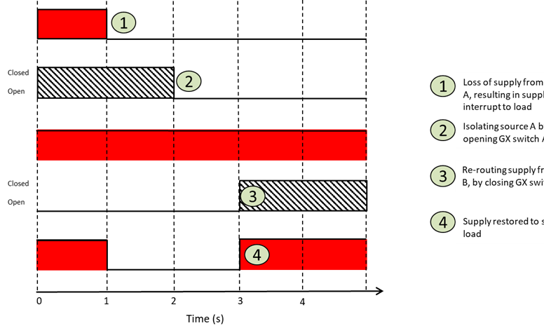
Figure 3: Illustration of ATS scheme
In addition to providing continuity of supply to the essential loads within 3-4 seconds, this particular application reduces need for additional primary and secondary equipment to achieve the ATS as well as making cost savings in the equipment and minimising any lost revenue.
Function block is a type of software component; the user is not required to have a detailed understanding of its internal working. The benefits of function block are becoming apparent to the user as these schemes become a standard function that can be applied. Additionally there are no ‘software’ variables that can exist outside the function blocks, making them portable. This is an important distinction between IEC 61499 and IEC 61131.